Hacking The Ritto TwinBus 7630
How to press a buzzer via TCP/IP.
Contents
# Introduction
If you're like me you firmly believe that appliances should be dumb instead of smart, but sometimes there is no other way. So lets talk about it and show you how to add IP networking to a Ritto TwinBus intercom system.
I will guide you through the four parts:
- the building's intercom hardware
- the custom hardware to interface with the building
- the hardware to install in our main office (spoiler: its a Raspberry Pi)
- the software to tie it all together
The good news is that we don't have to write any software by ourselves, just write some YAML and click buttons in Home Assistant.
# The Problem
We have two office rooms that are close by but located in separate buildings. Only one of them has a door bell, unfortunately it is the one where we are less often. So we need to be able to do two things from that other office room:
- get notified when someone rings the door
- be able to open the door remotely
An old-school intercom does this by ringing a bell, and offering a button you can press to activate the door opener. Somehow we must interface with those signals and route them over the network.
# The Building Intercom
The specific model we have installed is the Ritto 7630, which is common in Germany. The manufacturer does not offer any IP networking addons, I imagine this must be because they hate making money, so we have to roll our own.
Luckily a friendly electrician has published partial schematics on his website, which tells us which signals we need to interface with:
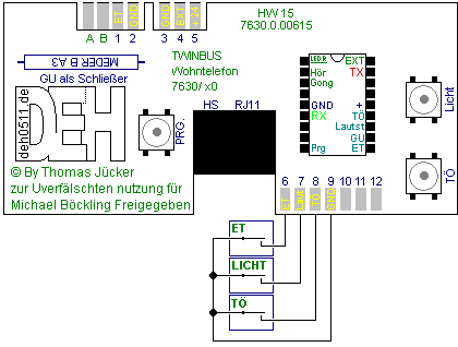
We need the following pins:
- 3 for ground
- 4 for the bell signal
- 8 for the buzzer
𝕬𝖈𝖍𝖙𝖚𝖓𝖌: The Ritto TwinBus system is very sensitive and easily jammed, or worse damaged. You should never power custom devices off the bus, as it can only supply a very limited amount of current. Doing so might take down the hole system or make operation even more unreliable than it already is. You should also aim to electrically isolate your device, unless you know what you are doing.
# Interface Hardware
We'll use the Adafuit HUZZAH ESP8266 due to its small physical size, running the ESPHome firmware. Flash it using the following YAML:
esphome:
  name: keilerkonzept-doorbell

esp8266:
  board: huzzah
  framework:
    version: recommended

# Enable logging
logger:

# Enable Home Assistant API
api:
  password: ''

ota:
  password: ''

wifi:
  ssid: Keilerkonzept
  password: some_pass

# Enable fallback hotspot (captive portal) in case wifi connection fails
ap:
  ssid: doorbell-fallback-ap
  password: some_pass

binary_sensor:
  - platform: gpio
    pin:
      number: 12
      inverted: true
      mode:
        input: true
        pullup: true
    id: doorbell
    name: Doorbell
    device_class: window
    filters:
      - delayed_off: 10ms

output:
  - platform: gpio
    pin: 13
    id: open_door_output

button:
  - platform: output
    id: open_door
    name: Open Door
    icon: 'mdi:door'
    output: open_door_output
    duration: 500ms
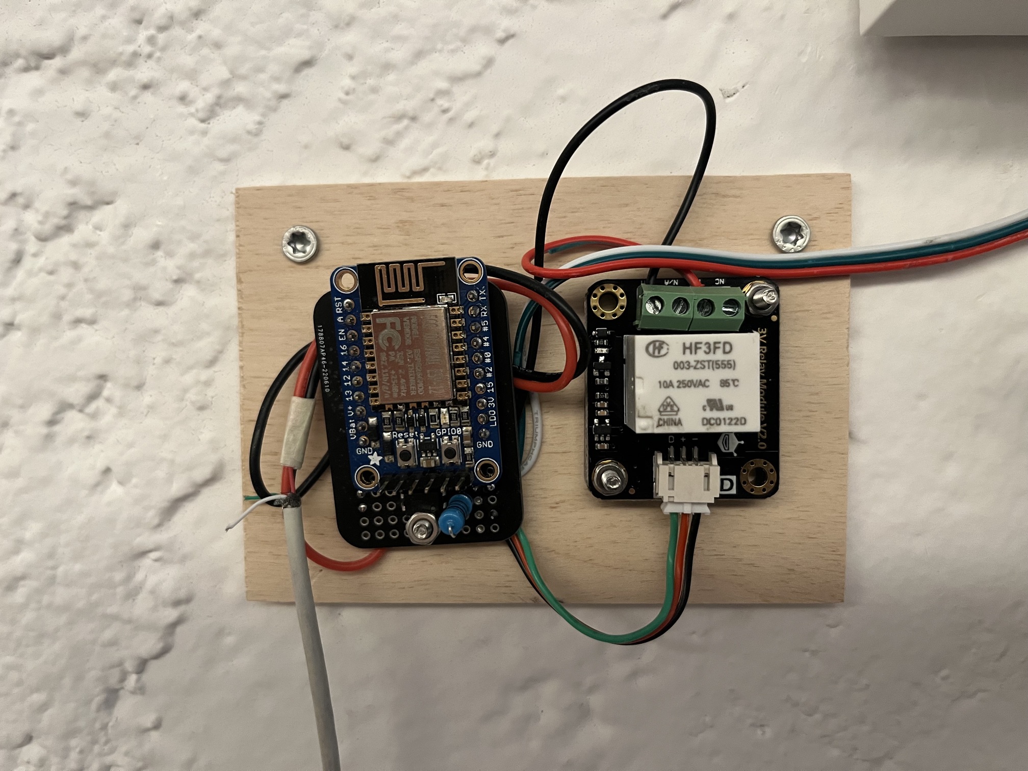
This is the list of parts that you need for the custom interface board:
- Adafruit HUZZAH ESP8266 due to its small footprint
- GeeekPi 5Pack Mini Proto Breadboard
- DFRobot DFR0473 digital relay
- PC817C optocoupler
- 1W 1KOhm resistor
- Lumberg 3-pole PCB edge connector
- some wires, screws and plugs as desired
The ESP8266 must be powered by its own USB power supply, and should be isolated from the intercom by using an opcto-coupler and a relais.
Solder the ESP8266 onto the protoboard with the back aligned to the edge, so that there is still space at the other end to place the rest of the components. Solder the optocoupler onto the board, connect the output pins to pin 12 of the ESP8266, and add the 1k resistor to the optocoupler's input side. Connect the relay to the ESP8266 pin 13, don't forget to connect ground for both.
As you can see, only three wires are needed from the pcb to the intercom: bell, buzzer and ground.
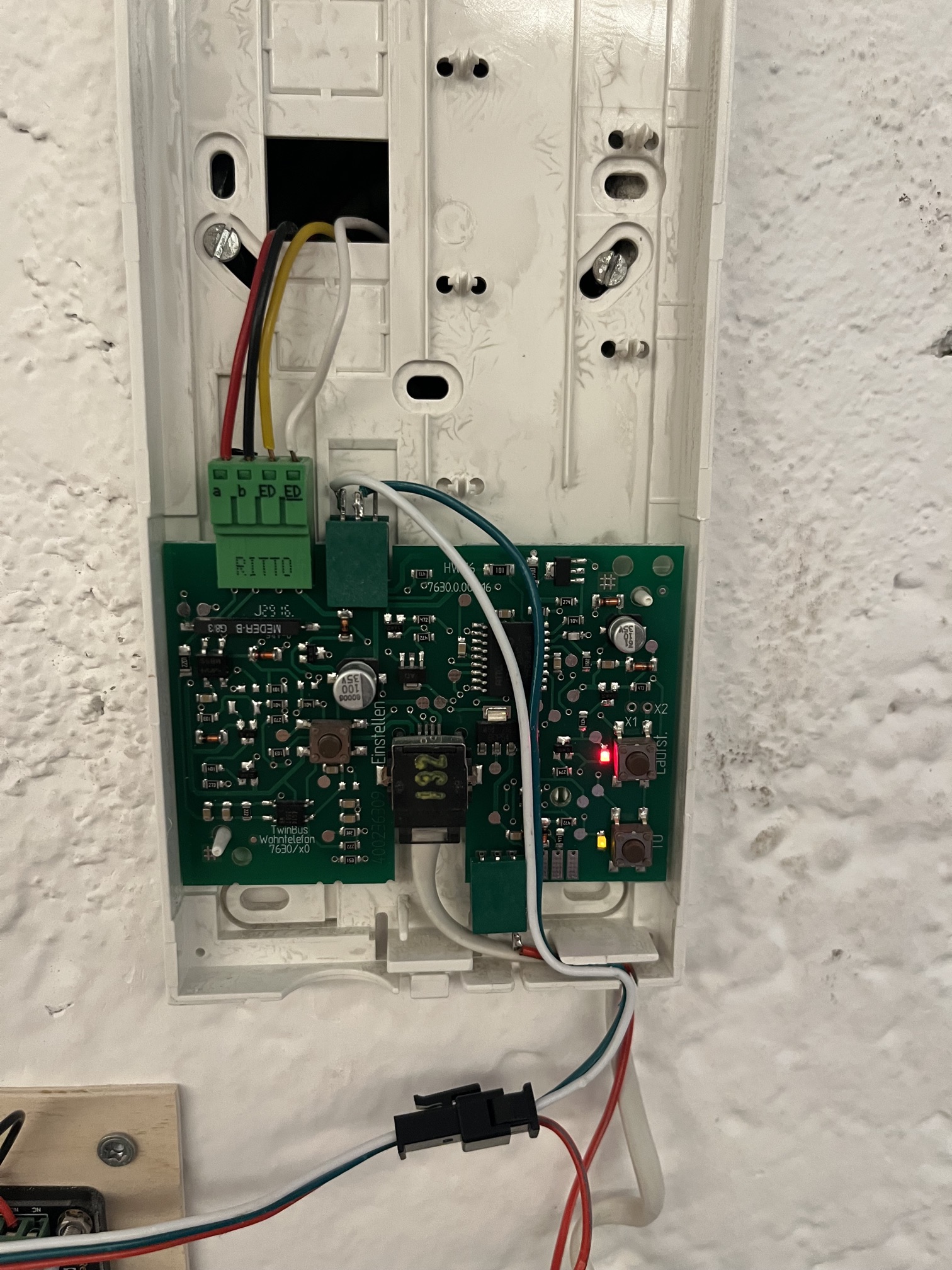
The plastic casing of the Ritto intercom is easy to remove. First remove the upper left connector, so that while you work, you will by accident cause a short and disable the whole system. Solder the wires to the pcb edge connectors, and place them in the right location.
# Connecting the routers
The wifi connection for the intercom goes to a Fritzbox router, which is connected via Wireguard to another Fritzbox that is located in the main office. You can connect your routers anyway you like, but I found that Wireguard works well and is easy to setup.
# Remote Station in Main Office
Its a Raspberry Pi with Home Assistant on it. There are two ways to install HA, one takes over the whole system, another runs HA as Docker container. If you want to run other things on it, you should not choose the first option, but if not, this is the simplest and sure to work. The custom Docker container mode is limited by default, eg you cannot install extensions, but this can be worked around with a little effort (out of scope).
You will need:
- Raspberry Pi (choose a model that is recommended by Home Assistant)
- Adafruit I2S 3W Stereo Speaker Bonnet for Raspberry Pi
- a small speaker
Install the Bonnet to the Pi as described in the manual, and attach the speaker. Once you got the hardware setup, it is time to setup Home Assistant.
- Setup Home Assistant
- Add the ESPHome integration
- add the Alsa & PulseAudio Fix
- add the Terminal & SSH addon, so that you have shell access inside HA
- add a shell command to
/config/configuration.yaml, so you can play a sound locally (which weirdly isn't straightforward to do by default):
shell_command:
    play_sound: ffplay -loglevel quiet -nodisp -vn -autoexit /media/bell.wav
- upload your favourite bell sound to
/media/bell.wav
When the ESP8266 is running on the same network, it should be auto-discovered via mDNS. If not, you'll have to manually add its IP address. Fine-tune the name of your entities and rooms in Home Assistant, and then add an automation to the doorbell:
- trigger: doorbell opened
- conditions: none
- actions: shell command > play_sound
If you have setup everything correctly, ringing the door will play a sound on your Pi, and you can activate the buzzer via the web interface. After operating this setup for some months, I can report that it works rock solid and has no glitches or autoages whatsoever.
This is just a rough guide with some small details not explicitly spelled out, but it should get you started.